introduction
The flow coefficient is one of the fundamental parameters in the design and selection of safety valves and has a direct impact on the performance and safety of pressurized systems. This parameter, commonly referred to as Cd or Kd, expresses the relationship between the actual flow rate passing through the valve and the calculated theoretical flow rate. and methods of its accurate calculation.
Technical Definition of Discharge Factor
The coefficient of consumption is mathematically determined as follows:
Cd = Actual Consumption / Theoretical Consumption
This ratio is always less than 1 (usually between 0.6 and 0.98) and indicates how much the actual performance of the valve deviates from the ideal level. Its exact value depends on a number of factors, which we will discuss in detail below.
Reasons for the Importance of Flow Coefficient in Safety Valve Design
1. Accuracy of milk yield calculation.
The flow coefficient has a direct impact on the size of the safety valve. Failure to take this parameter into account can lead to the selection of a valve with insufficient flow capacity.
2. Compressed Systems Safety
Inaccurate calculations due to inaccurate flow coefficients can expose the system to the risk of overpressure.
3. Cost optimization
Choosing a valve with too much flow capacity due to a conservative flow rate leads to unnecessary costs.
4. Compliance with Industry Standards
Standards such as API 520 and ASME particularly emphasize the need to use the correct consumption coefficient values.
Factors Affecting the Consumption Factor
1. Mechanical valve design.
-
Valve type (mechanical, piston, diaphragm)
-
Designing Flow Paths
-
Roughness of the inner surface
-
angle
2. Properties of liquids
-
Joe
-
density
-
Liquid phase (liquid, gas, or two phases)
-
temperature
3. Operating Conditions
-
Pressure Rise Rate
-
Disc Lift (Elevator)
-
Ratio of Inlet and Outlet Pressures
4. Environmental Impact
-
corrosion
-
corrosion
-
sedimentation
Methods for determining the coefficient of consumption
1. Pilot tests
Many manufacturers of safety valves determine the flow coefficient of their products through practical tests. This method provides the most accurate results.
2. Use Industry Standards
Several standards provide default values for the discharge rate:
-
API 520: Typically 0.975 for gases and vapors
-
ASME Section VIII: 0.62 for liquids
3. Computational fluid dynamics calculations
Computational fluid dynamics (CFD) simulations can be used to predict the coefficient of flow in new designs.
4. Quasi-experimental methods
There are some empirical relationships, such as the equations given by Crane or Darby, for estimating the coefficient of consumption.
Effect of Consumption Factor on Volume Calculations
To understand the practical significance of the flow coefficient, let’s look at the basic equation for calculating the sizing of gas relief valves:
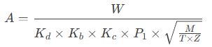
Where is:
-
A: Required cross-sectional area
-
W: Flow rate
-
Cd: Consumption coefficient
-
Kb: Back pressure correction factor
-
P1: Inlet pressure
-
M: Molecular Weight
-
T: Absolute Temperature
-
Z: Compression Ratio
As you can see, the flow coefficient is included directly in the denominator of the equation. Therefore:
-
An increase in cadmium content leads to a decrease in the required cross-sectional area.
-
To reduce Cd, it is necessary to choose a valve with a large cross-section.
Practical Problems of Using Coefficients of Consumption
1. Change in Consumption Coefficient Over Time
Factors such as wear, corrosion, and dirt can change the flow rate over time .
2. Uncertainty of operating conditions
Changes in fluid properties or operating conditions can affect the flow coefficient.
3. Limitations of laboratory data
For many specific valves or unusual operating conditions, experimental data are insufficient.

Engineering solutions for the control of discharge plants
1. Apply Safety Factor
To ensure proper operation, use a more conservative discharge ratio than the manufacturer’s recommended values.
2. Periodic Inspection Programs
Periodically check the mechanical condition of the valve to ensure that the flow rate is stable.
3. Periodic calibration
Perform performance tests to verify the actual performance of the valve.
4. Use smart faucets
Use valves equipped with sensors to monitor performance at all times.
Case studies
Case 1: Wrong Discharge Factor Selection in the Oil Industry
At the refinery, the use of an insufficient pressure relief ratio (0.85 instead of the actual 0.75) led to the selection of a relief valve with a capacity 13% less than the actual demand, which led to an emergency situation where the system failed to release the excess pressure in time.
Case study 2: Improving systems in the petrochemical industry
By conducting detailed tests to determine the actual flow rate of the valves, the petrochemical plant was able to increase the capacity of the system by 15% without the need to replace the valves.
Discharge Rate Standards
-
API 520 Part 1 : Includes calculation methods and recommended consumption factor values.
-
ASME Boiler and Pressure Vessel Standard Section 8 : Safety Valve Flow Coefficient Requirements
-
ISO 4126-1 : International Standard for Safety Valves
-
EN ISO 23251 : European Standard for Pressure Relief Systems
conclusion
The pressure relief ratio is a key criterion in the design and selection of safety valves, as it directly affects the safety, performance , and profitability of pressure systems. Engineers must perform accurate parameter calculations, fully understand the factors that affect it, and use sound methods to determine its value. parameter throughout the life cycle of the equipment can prevent operational and safety issues from occurring. Ultimately, working closely with valve manufacturers and using reliable laboratory data is critical to achieving optimal results when designing pressure relief systems.