Safety valves are essential in metering pump systems because they prevent overpressure. Choosing the right safety valve is crucial, as an incorrect valve can impair system performance, damage equipment, and even pose safety risks. This article explains how to calculate the correct safety valve for a metering pump.
The importance of choosing the right safety valve
Selecting the correct pressure relief valve for your dosing pump is crucial for the following reasons:
-
System protection : Prevents destructive pressure that could damage the pump and other equipment.
-
Increased productivity : Ensuring optimal operation of the dosing system.
-
Reduced maintenance costs : Avoid premature breakdowns .
-
Safety compliant : Meets legal and industry standards.
-
Improving energy efficiency : Avoiding energy losses in the system.
Basic criteria for calculating the dimensions of a safety valve
The following criteria must be taken into account to calculate the appropriate size of the pressure relief valve:
1. Consumption
-
nominal delivery rate of the pump
-
Maximum possible flow rate
-
Units of measurement (gallons per minute, cubic meters per hour, liters per minute, etc.).
2. System pressure
-
normal operating pressure
-
Pressure relief valve for pressure regulation
-
Counterpressure
-
Maximum allowable system pressure (MAWP)
3. Properties of liquids
-
density
-
atmosphere
-
Physical and chemical properties (corrosion, toxicity, particulate matter, etc.).
-
Liquid phase (liquid, gaseous or both)
4. Types of safety valves
-
spring-loaded safety valve
-
Piston-type safety valve
-
Diaphragm pressure relief valve
Method for calculating the volume of a safety valve.
API Standard Method 520
The method proposed by the American Petroleum Institute (API) is one of the most reliable methods for calculating the size of safety valves. The general formula is as follows:
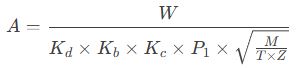
Where:
-
A: Required cross-sectional area (in square inches)
-
Flow rate (lbs/h)
-
Kd: Flow coefficient
-
Kb: Backpressure correction factor
-
Kc: Composition coefficient
-
P1: Inlet pressure (psia)
-
M: Molecular mass of the liquid
-
T: Absolute temperature of the liquid (°R)
-
Z: Pressure coefficient
Methodology of the ASME Boiler and Pressure Vessel Code
This method is applicable to printing systems and the calculation formula is as follows:

Where:
-
P: Flow rate (GPM)
-
G: Relative density of the liquid (compared to water)
-
Kd: Flow coefficient
-
kW: Backpressure correction factor
-
Kv: Viscosity index
-
ΔP: Pressure difference (psi)
Simplified dosing methods using pumps.
For dosing pumps, the following simpler method can be used:
-
Specify the maximum pump flow rate (Q_max).
-
Install the safety valve ( P_set).
-
Specify the back pressure (P_back) of the system.
-
Calculate the required power using the following formula:
Throughput = Q_{max} × (P_{set}} / (P_{set} – P_{back}})
-
Select a pressure relief valve with a flow rate equal to or greater than the design value.
Practical steps for calculating the size of safety valves.
The first step is to collect the necessary data.
-
Technical characteristics of the dosing pump (flow rate, pressure, power, etc.).
-
Performance diagram of the water pump
-
Properties of liquids ( density , viscosity and other properties)
-
Environmental conditions (temperature, altitude, etc.)
-
Piping and system layout diagram
Second step: Identify key scenarios
-
Identify all situations that could increase your stress level.
-
Calculate flow rate and pressure for each case.
-
Determine the worst-case scenario.
Step 3: Calculate the initial size
-
Choose the appropriate calculation method (API, ASME or other methods).
-
Insert the coefficients into the appropriate formula.
-
Calculate the required cross-sectional area.
Step 4: Select a safety valve from the manufacturer’s product catalog.
-
Compare the calculation results with the manufacturer’s product catalog.
-
An appropriate safety margin (usually 10 to 25%) should be provided.
-
Please select the nearest standard size.
Step 5: Reviewing the calculation results
-
The results were verified by experienced engineers.
-
Compared to similar systems
-
Please make any necessary corrections.
Factors that influence the final decision
In addition to theoretical calculations, the following factors should also be taken into account when selecting the final size of the pressure relief valve:
-
Cost issues : Balance between acquisition and operating costs.
-
Availability : Standard sizes are available in stores.
-
Space limitations : Considerations for on-site installation.
-
Maintenance instructions : Easy to repair and maintain.
-
Future flexibility : the ability to change the system in the future.
Calculate the size of the safety valves for the respective application.
High-viscosity system
For highly viscous liquids, a viscosity correction factor (Kv) must be included in the calculations. This factor is usually determined using standard tables.
Systems containing corrosive fluids
In such cases, in addition to dimensioning calculations, it is also necessary to carefully select the materials used in the manufacture of the safety valve in order to ensure their corrosion resistance .
System with variable back pressure
In the case of variable back pressure in the system, a balanced pressure relief valve should be used, and calculations should be based on the maximum back pressure.
Common mistakes when dimensioning a safety valve
-
Ignoring back pressure : This error can lead to selecting a pressure relief valve that is too small .
-
Use the nominal flow rate instead of the maximum flow rate : Always assume the worst-case scenario.
-
Changes in viscosity with temperature were not taken into account , especially for liquids where viscosity is closely related to temperature.
-
Ignoring the water hammer effect : This effect can be significant in systems subject to sudden changes in flow rate.
-
Choosing an oversized system : This can lead to increased costs and system instability.
The program used for the calculation.
There are currently many computer programs specifically designed for the dimensioning of safety valves; some of the best-known are listed below:
-
Valve Size Calculator (VSC)
-
Aspen Torch System Analyzer
-
Siemens SIPART PS2 measuring device
-
Fisher control valve solutions
-
Emerson PRV2 size
These programs deliver more accurate calculation results because they take all permissible criteria into account.
Relevant standards
Important criteria to consider when dimensioning and selecting a safety valve include the following:
-
API 520 : Sizing, selection and installation of relief devices.
-
API 526 : Flanged steel safety valve
-
Section 8 of the American Society of Mechanical Engineers Standards : Pressure Vessels
-
ISO 4126 : Protective devices for overcurrent protection
-
ANSI/ASME PTC25 : Safety devices
In conclusion
Calculating the optimal size of a pressure relief valve for a metering pump is a highly specialized task requiring in-depth knowledge of system parameters, fluid properties, and technical principles. Choosing the wrong size can have serious consequences, such as reduced system efficiency, increased maintenance costs, and even safety risks. By adhering to standardized procedures and considering all relevant factors, you can select the optimal pressure relief valve for your metering pump system. If you have any questions regarding the calculations, we recommend consulting a qualified engineer.